Specialists in Mechanical Testing and Reliability of Optical Fibers
![]()
![]()
![]()
![]()
![]()
![]()
Specialists in Mechanical Testing and Reliability of Optical Fibers
|
|
|
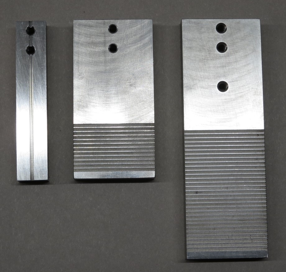
Faceplates for Two-Point Bend TesterThe faceplates are the most important part of the two-point bend tester - they hold the fiber(s) during loading to failure. The precision of the measurement depends on the precision of the faceplates...and the precision of their alignment. (Alignment procedures are described in the 2POINT for Windows User's Manual.) Faceplate GroovesTypically the fiber is supported by grooves in the faceplates. We have now standardized on 90° "V" grooves. These accurately locate the fiber in a plane perpendicular to the faceplates and can accommodate a broad range of fiber outer diameters (coating diameters). See the photograph below.
(click photograph for a bigger image) Originally we used "U" grooves with flat bottoms - it is a little easier to machine these grooves and to measure their depth. However, they are limited in the coating diameters they can accept. If the diameter is bigger than the width of the grooves, the fiber will not sit on the bottom of the grooves. If the diameter is somewhat smaller than the width of the grooves, the fiber will sit cocked at an angle in the opposing grooves giving an error in the strength inferred from the faceplate separation at failure. We do have a limited stock of U-groove faceplates available if you prefer them - please contact us for information. Multi-Groove FaceplatesThe standard faceplates supplied with the Two-Point Bend Tester each have a single groove meaning that only one fiber can be tested at a time. Multi-groove faceplates permit testing multiple fibers at once, speeding testing. However, fracture of the fibers is detected by the acoustic signal (the faint click you hear when breaking fibers manually). When testing at high speed the acoustic signals from two or more fibers might overlap. The acoustic detection system can not distinguish this and only the first break will be recorded. This results in missed breaks and, problematically, the detected break corresponds to the weakest of the overlapping breaks and therefore there is some bias in the result. For this reason, only one fiber should be tested at a time for high loading rates. More fibers can be tested for slower loading rates. It is recommended that at least 90% of breaks are detected. If you are missing too many breaks, we recommend you reduce the number of fibers tested simultaneously. In practice this means that all grooves of multi-groove faceplates should only be used for the slowest loading rates. Note that there is some variability in the groove depths of multi-groove faceplates so it is recommended that all grooves are used equally - i.e. when testing a group of fibers one fiber at a time, don't keep using the same groove - use all grooves equally. The variability in the groove depth is small and statistically insignificant under almost all circumstances, but we recommend avoiding any possible source of systematic error, if only for peace of mind!
The photograph above shows the available multi-groove faceplate options.
The groove depth in each faceplate is typically 500-600 μm with a combined depth of 1000-1200 μm for a pair of faceplates. Special Purpose FaceplatesWhile the multi-groove faceplates significantly decrease total testing time over testing one fiber at a time, we recommend use of the Automatic Fiber Loader as an alternative. The auto loader only tests one fiber at a time but it wastes no time between measurements and requires minimal operator time - the operator just needs to load a length of fiber ready for a test sequence and then collect the data when a test sequence is finished. The operator can therefore be performing other tasks while, for example, a fatigue test is performed where the fiber is broken multiple times at a range of loading rates. The 2POINT software can be easily configured to send the operator status updates on the progress of testing, to report any errors and, when a measurement is complete, it will send a message including the resulting data. Given the most significant overhead cost of the Two-Point Bend System is operator time, the auto loader represents a substantial return on investment (ROI).
Other advantages of using the auto loader include better randomization of testing. When maually loading fiber there is a temptation to make all the rapid tests first and the slowest measurements last (which might take order one hour each). Any drift in the testing environment (temperature and humidity) would apply a systematic bias to the results perturbing the measured value of the stress corrosion susceptibility parameter, n. In contrast, the auto loader will run one measurement at each loading rate, then repeat that sequence until all the required measurements are finished (for example a total of 15 measurements at each of four loading rates). Interleaving the measurements at each rate like this averages out the influence of test environment fluctuations and avoids any bias in the measured value of n. Another advantage of the auto loader is that it only uses one groove depth - there is some variation in the groove depth in multi-groove faceplates which add a most amount of scatter t=in the resulting data - this is avoided using single groove faceplates.
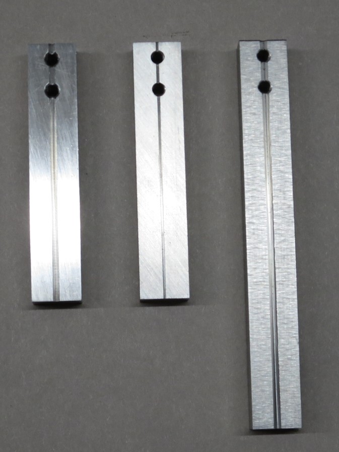
The photograph above shows the available faceplate options for use with the Automatic Fiber Loader.
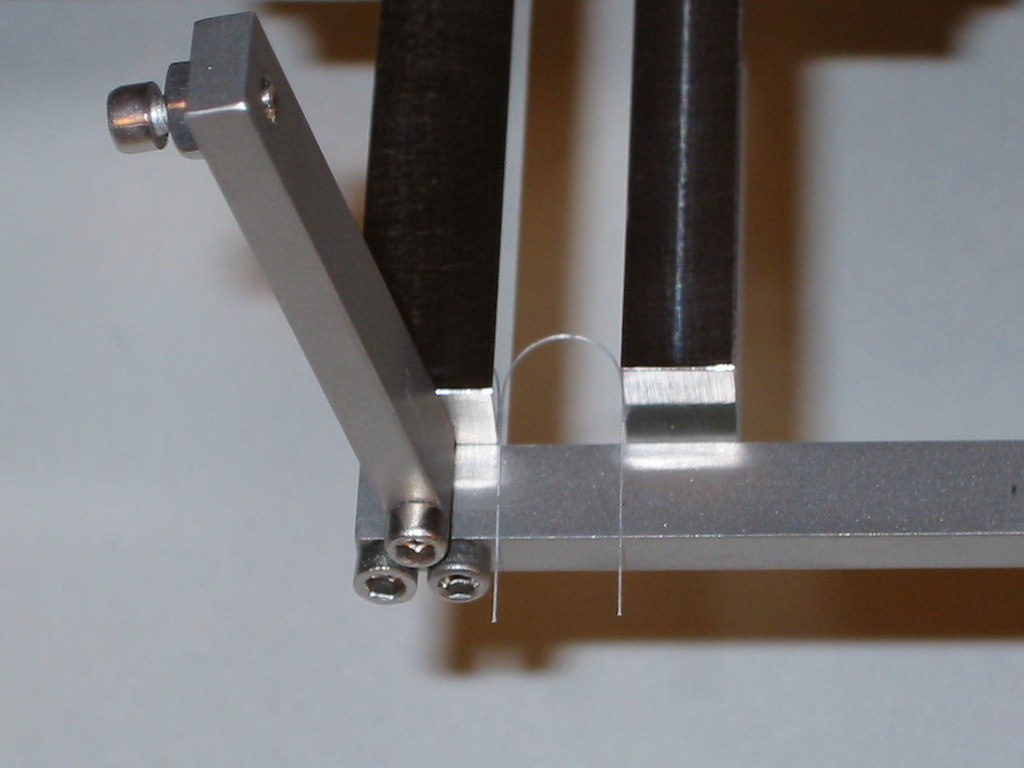
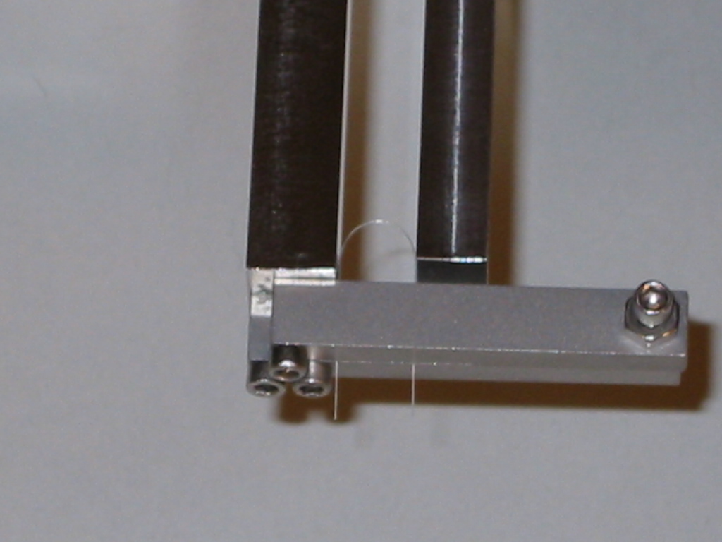
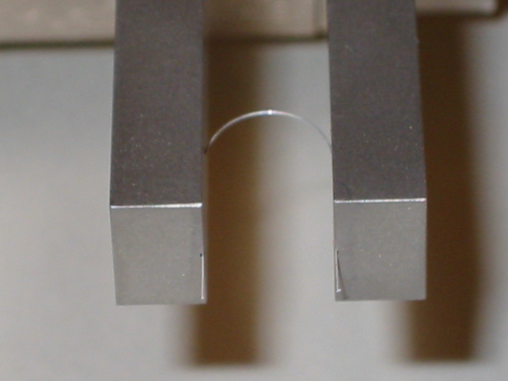
Polished Faceplates - Grooveless FaceplatesIt is well known that the chemistry and adhesion of the polymer coating affect the mechanical properties of the glass surface - both the strength and n. It can be very useful to know the strength of the bare glass surface but this leads to severe difficulties handling the fiber since any incidental contact with the bare glass surface will dramatically decrease its strength. Similarly it is not possible to make bare optical fiber without surface degradation. The approach taken by researchers has been to remove the polymer coating chemically using either methylene chloride or hot concentrated sulfuric acid. Two-point bend testing is an appropriate method for measuring the strength of bare fiber because the shape of the fiber (an "elastica") gives a maximum stress in the fiber at the "tip" of the bend but the stress decreases with distance from the tip until it is nominally zero where the fiber contacts the faceplates. Reference 1 contains details of the stress analysis. The fiber is carefully balanced between two "polished" faceplates using two guide plates to hold the fiber perpendicular to the faceplates, as shown below.
These optional faceplates (part number FP-POL) are called "polished" faceplates because their faces are very smooth, but might actually be ground rather than polished. See the maintenance hints below. Faceplate MaintenanceSome suggestions for maintaining faceplates:
|
|